今回は製品への表示シリーズ2回目として, 欧州CEマーキングにおけるLVD指令(2014/35/EU)とLVD指令における整合規格 EN 61010-1: 2010/A1:2019にて要求されている製品に表示が必要な項目についての調査結果の記事になります。ご参考ください。
※いつものとおり内容を保証するものではありませんので詳細は規格原文をご確認ください。
LVD指令(2014/35/EU)における要求事項
LVD指令における第6条(該当5項〜7項)と第17条に製造業者への表示に関する要求事項について記載があり, 以下内容について装置への記載を要求しています。
表示要求1: 機器を識別するための情報
2014/35/EU Article 6 Obligations of manufacturers
2014/35/EU第6 条 メーカーの義務
5. Manufacturers shall ensure that electrical equipment which they have placed on the market bears a type, batch or serial number or other element allowing its identification, or, where the size or nature of the electrical equipment does not allow it, that the required information is provided on its packaging or in a document accompanying the electrical equipment.
5. 製造業者は、市場に出した電気機器に、識別を可能にするタイプ、バッチまたはシリアル番号またはその他の要素を付けること、電気機器のサイズまたは性質によってそれができない場合は、必要な情報は、パッケージまたは電気機器に付属の文書に記載する。
表示要求2: 製造業者名、登録商標名または登録商標および連絡先の住所
2014/35/EU Article 6 Obligations of manufacturers
2014/35/EU第6 条 メーカーの義務
6. Manufacturers shall indicate on the electrical equipment their name, registered trade name or registered trade
mark and the postal address at which they can be contacted or, where that is not possible, on its packaging or in a document accompanying the electrical equipment.
The address shall indicate a single point at which the manufacturer can be contacted. The contact details shall
be in a language easily understood by end-users and market surveillance authorities.
6. 製造業者は、電気機器に製造業者の名前、登録商標名または登録商標および連絡先の住所を表示するか、それが不可能な場合は、
そのパッケージまたは電気機器に付属する文書に表示するものとします。
住所は、製造業者に連絡できる一元管理された連絡先を示すものとします。
連絡先の詳細は、エンドユーザーおよび市場監視当局が容易に理解できる言語でなければなりません。
表示要求3: 安全上必要な情報
2014/35/EU Article 6 Obligations of manufacturers
2014/35/EU第6 条 メーカーの義務
7. Manufacturers shall ensure that the electrical equipment is accompanied by instructions and safety information in a language which can be easily understood by consumers and other end-users, as determined by the Member State concerned. Such instructions and safety information, as well as any labelling, shall be clear, understandable and intelligible.
7.製造業者は、電気機器に、消費者が容易に理解できる言語で説明書と安全情報を添付することを保証するものとします。そのような指示と安全情報、およびラベルは、明確で、理解しやすく、理解しやすいものでなければなりません。
表示要求4: CEマーク
2014/35/EU Article 17 Rules and conditions for affixing the CE marking
2014/35/EU第17条 CEマーキング貼付のルールと条件
1. The CE marking shall be affixed visibly, legibly and indelibly to the electrical equipment or to its data plate. Where that is not possible or not warranted on account of the nature of the electrical equipment, it shall be affixed to the packaging and to the accompanying documents.
1. CE マーキングは、電気機器またはそのデータ プレートに、見やすく、読みやすく、消えないように貼付する必要があります。電気機器の性質上、それが不可能または保証されない場合は、パッケージおよび添付文書に添付するものとします。
EN 61010-1: 2010/A1:2019における要求事項
EN 61010-1: 2010/A1:2019に関しては5.1.2項〜5.2項に電気機器への表示の要求事項についての記載があり, 以下内容について電気機器への記載を要求しています。
※以下は規格の文言を抜粋しておりますが, 一部表記を省略している箇所もありますので詳細は規格原文をご確認ください。
表示要求1: 機器を識別するための情報
5.1.2 Identification
The equipment shall, as a minimum, be marked with:
a) the name or trade mark of the manufacturer or supplier;
b) a model number, name or other means to identify the equipment.
If equipment bearing the same distinctive designation (model number) is manufactured at more than one location, equipment from each manufacturing location shall be marked so that the location can be identified.
NOTE The marking of factory location may be in code and need not be on the equipment exterior.
5.1.2識別
機器には,少なくとも次のa) 及びb) の事項を表示する。
a) 製造業者又は供給者の,名称又は登録商標
b) 機器を識別するための形名,名称その他の手段。
同一の識別名(形名)を付けた機器を二か所以上の場所で製造する場合、機器には製造場所が識別できるように表示する。
注記 製造場所は,コード(符号)で表示してもよい。また,機器外面以外の箇所に表示してもよい。
表示要求2: 主電源に関する情報
5.1.3 MAINS supply
The equipment shall be marked with the following information.
a) Nature of supply:
1) a.c.: RATED MAINS frequency or range of frequencies;
2) d.c.: symbol 1 of Table 1.
NOTE 1 For information purposes it may be useful to mark
– equipment intended for a.c. with symbol 2 of Table 1;
– equipment suitable for both a.c. and d.c. with symbol 3 of Table 1;
– equipment for three-phase supply with symbol 4 of Table 1.
b) The RATED supply voltage(s) or the RATED range of supply voltages.
c) The maximum RATED power in watts (active power) or volt-amperes (apparent power), or the maximum RATED input current, with all accessories or plug-in modules connected.
d) Equipment which an OPERATOR can set for different RATED supply voltages shall be provided with means for the indication of the voltage for which the equipment is set.
For PORTABLE EQUIPMENT the indication shall be visible from the exterior.
If the equipment is so constructed that the supply voltage setting can be altered without the use of a TOOL, the action of changing the setting shall also change the indication.
e) Accessory MAINS socket-outlets accepting standard MAINS plugs shall be marked with the voltage if it is different from the MAINS supply voltage. If the outlet is for use only with specific equipment, it shall be marked to identify the equipment for which it is intended.
If not, the maximum RATED current or power shall be marked, or symbol 14 of Table 1 placed beside the outlet with the full details included in the documentation.
5.1.3 主電源
機器には,次の情報を表示する。
a) 電源の種類
1) 交流:定格電源周波数又は定格周波数範囲
2) 直流:表1に示す番号1の記号
注記1 情報として,次の記号を表示するのがよい。
−交流用機器には,表1に示す番号2の記号
−交直両用機器には,表1に示す番号3の記号
−三相交流機器には,表1に示す番号4の記号
b) 定格電源電圧又は電源電圧の定格範囲
c) 全ての附属品及びプラグインモジュールを接続した状態での,ワット(W:有効電力)若しくはボルトアンペア(VA:皮相電力)で表した最大定格電力,又は最大定格入力電流。
d) 操作者が異なる定格電源電圧を設定できる機器は,機器の設定電圧を表示する手段を備えていなければならない。携帯形機器の場合,この表示は,外部からよく見えなければならない。工具を用いずに電源電圧設定を変更できる構造の機器の場合は,設定の変更操作によって,電源電圧の表示も同様に変わらなければならない。
e) 標準の主電源プラグに合う補助の電源アウトレットには,電圧が主電源電圧と異なる場合は,その電圧を表示する。このアウトレットを特定の機器にだけ用いる場合は,意図する機器を識別するための表示をする。特定の機器以外に用いる場合は,最大定格電流若しくは最大定格電力を表示するか,又はアウトレットの近くに表1に示す番号14の記号を付け,文書で詳細な説明をする。
表示要求3: ユーザーが交換できるヒューズの情報
5.1.4 Fuses
For any fuse which may be replaced by an OPERATOR, there shall be a marking beside the fuseholder, which will enable the OPERATOR to identify the correct replacement fuse (see 5.4.5).
5.1.4ヒューズ
操作者が交換できるヒューズは,ヒューズホルダの近くに,正しい交換ヒューズを操作者が特定できる表示がなければならない(5.4.5参照)。
5.4.5より以下抜粋
The RATING and characteristics of replaceable fuses shall be stated.
交換できるヒューズの定格及び溶断特性を,明記しなければならない。
表示要求4: 端子,接続及び操作デバイスの情報
5.1.5 TERMINALS, connections and operating devices
5.1.5.1 General
If necessary for safety, an indication shall be given of the purpose of TERMINALS, connectors, controls, and indicators, including any connections for fluids such as gas, water and drainage.
Where there is insufficient space, symbol 14 of Table 1 may be used.
Push-buttons and actuators of emergency stop devices, and indicators used only to indicate a warning of danger or the need for urgent action, shall be coloured red and coded as specified in IEC 60073. If the meaning of colour relates to the safety of persons or the environment, supplementary means of coding shall be provided (see IEC 60073).
5.1.5端子,接続及び操作デバイス
5.1.5.1一般
安全上必要な場合,ガス,水及び排水のような流体への接続を含め,端子,制御器及び指示器には,その目的を示す表示がなければならない。表示面積が不十分な場合は,表1に示す番号14の記号を用いてもよい。
緊急停止デバイスの押しボタン及び操作部,並びに危険に対する警告又は緊急行動の必要性を示すためだけに用いる表示器は,IEC 60073に規定するように赤にし,かつ,符号化しなければならない。色の意味が人体の安全性又はその周囲環境に関わる場合には,符号の補助手段を提供しなければならない(IEC 60073参照)。
5.1.5.2 TERMINALS
TERMINALS for connection to the MAINS supply shall be identifiable.
The following TERMINALS shall be marked as follows:
a) FUNCTIONAL EARTH TERMINALS with symbol 5 of Table 1;
b) PROTECTIVE CONDUCTOR TERMINALS with symbol 6 of Table 1,
except when the PROTECTIVE CONDUCTOR TERMINAL is part of an approved MAINS appliance inlet.
The symbol shall be placed on the TERMINAL or close to it;
c) TERMINALS of circuits which are permitted by 6.6.3 to be connected to ACCESSIBLE conductive parts, with symbol 7 of Table 1 unless connection is self-evident;
d) TERMINALS supplied from the interior of the equipment and which are HAZARDOUS LIVE, with the voltage, current, charge or energy value or range, or with symbol 14 of Table 1. This requirement does not apply to MAINS supply outlets where a standard MAINS socket outlet is used.
5.1.5.2端子
主電源へ接続するための端子は,識別可能でなければならない。
次の端子は,a)〜d) のように表示しなければならない。
a) 機能接地端子には,表1に示す番号5の記
b) 保護導体端子には,表1に示す番号6の記号
ただし,保護導体端子が,認証された機器用主電源インレットの一部である場合を除く。
記号は,端子上又は端子のすぐ近くに表示する。
c) 接触可能な導電性部分に接続することが6.6.3によって許容される回路の端子には,接続が自明でない限り,表1に示す番号7の記号
d) 機器の内部から給電される端子で,かつ,それが危険な活電部分でもある場合には,次のいずれかによる。− 電圧,電流,又は電荷若しくはエネルギーの値又は範囲− 表1に示す番号14の記号この要求事項は,標準の主電源コンセントに取り付けて用いる機器の主電源アウトレットには適用しない。
表示要求5: 電源ON,OFF位置の表示
5.1.6 Switches and circuit-breakers
If the power supply switch or circuit-breaker is used as the disconnecting device, the off-position shall be clearly marked.
NOTE It is recommended that the on-position also be marked.
Symbols 9 and 10 of Table 1 can, in some cases, also be suitable as the device identification (see 6.11.3.1 c)).
A lamp alone is not considered to be a satisfactory marking.
If a push-button switch is used as the power supply switch, symbols 9 and 15 of Table 1 may be used to indicate the on-position, or symbols 10 and 16 to indicate the off-position.
5.1.6 スイッチ及び回路遮断器
電源スイッチ又は回路遮断器を開放デバイスとして用いる場合は,オフ位置を明確に表示しなければならない。
注記 オン位置も表示することが望ましい。
表1に示す番号9の記号及び番号10の記号も,場合によっては開放デバイスの識別として適切である(6.11.4.2参照)。ランプだけによる表示では不十分である。
押しボタン式スイッチを電源スイッチとして用いる場合は,オフ位置を示すために表1に示す番号10の記号及び番号16の記号を表示してもよい。オン位置を示すために番号9の記号及び番号15の記号を表示してもよい。
表示要求6: 二重絶縁又は強化絶縁機器の場合の表示
5.1.7 Equipment protected by DOUBLE INSULATION or REINFORCED INSULATION
Equipment which is only partially protected by DOUBLE INSULATION or REINFORCED INSULATION shall not be marked with symbol 11 of Table 1.
NOTE Equipment protected throughout by DOUBLE INSULATION or REINFORCED INSULATION may be marked with symbol 11 of Table 1.
5.1.7 二重絶縁又は強化絶縁によって保護する機器
二重絶縁又は強化絶縁によって部分的にだけ保護する機器には,表1に示す番号11の記号を表示してはならない。
注記 二重絶縁又は強化絶縁によって全体を保護する機器には,表1に示す番号11の記号を表示してもよい。
表示要求7: 端子又は外装の温度が正常状態で60 ℃を超える場合の配線端子箱への表示
5.1.8 Field-wiring TERMINAL boxes
If the temperature of the TERMINALS or the ENCLOSURE of a field-wiring TERMINAL box or compartment exceeds 60 °C in NORMAL CONDITION at an ambient temperature of 40 °C, or at the maximum RATED ambient temperature if higher, there shall be a marking to warn the installer to consult the installation instructions before determining the temperature RATING of the cable to be connected to the TERMINALS. The marking shall be visible before and during connection, or be beside the TERMINALS. Symbol 14 is an acceptable marking.
5.1.8現場配線端子箱
周囲温度40 ℃,又は最大定格周囲温度が40 ℃よりも高い場合はその温度で,現場配線端子箱又は端子収納部の,端子又は外装の温度が正常状態で60 ℃を超える場合には,端子に接続するケーブルの温度定格を決める前に設置説明書を参照することを設置者に警告する表示をしなければならない。表示は,接続前及び接続中によく見えるか,又は端子の近くとする。表1に示す番号14の記号を表示してもよい。
表示要求8: 正常な使用のために必要な警告表示
5.2 Warning markings
Warning markings specified in this standard shall meet the following requirements. Warning markings shall be visible when the equipment is ready for NORMAL USE. If a warning applies to a particular part of the equipment, the marking shall be placed on or near that part.
The size of warning markings shall be as follows:
a) symbols shall be at least 2,75 mm high. Text shall be at least 1,5 mm high and contrast in colour with the background;
b) symbols or text moulded, stamped or engraved in a material shall be at least 2,0 mm high.
If not contrasting in colour, they shall have a depth or raised height of at least 0,5 mm.
5.2警告表示
この規格に規定する警告表示は,次の要求事項を満たさなければならない。機器が正常な使用のための準備ができているとき,警告表示はよく見えなければならない。警告を機器の特定の部分に適用する場合は,表示はその部分か又はその部分の近くになければならない。
警告表示の方法は,次のa)又はb)とする。
a) 記号の高さは2.75 mm以上,文字の高さは1.5 mm以上で,背景と色彩的にコントラストがある。
b) 材料に成形,刻印又は彫刻する場合は,記号及び文字の高さは,2.0 mm以上とする。
色彩的にコントラストがない場合は,記号及び文字は,0.5 mm以上の深さ又は盛上げとする。
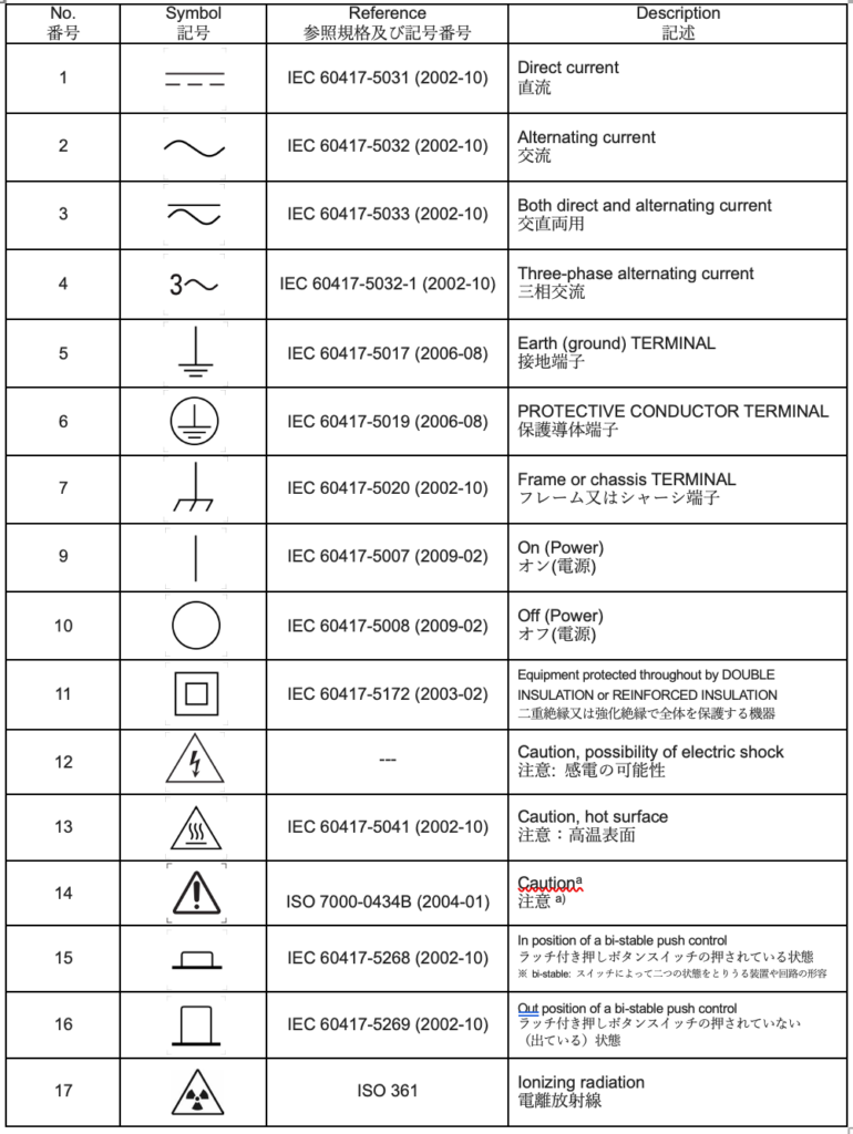
EN 61010-1: 2010/A1:2019にて参照される警告および図記号
警告および図記号についてはEN 61010-1: 2010/A1:2019の表1に記載されています。
EN 61010-1: 2010/A1:2019 Table 1 – Symbols 表1−記号
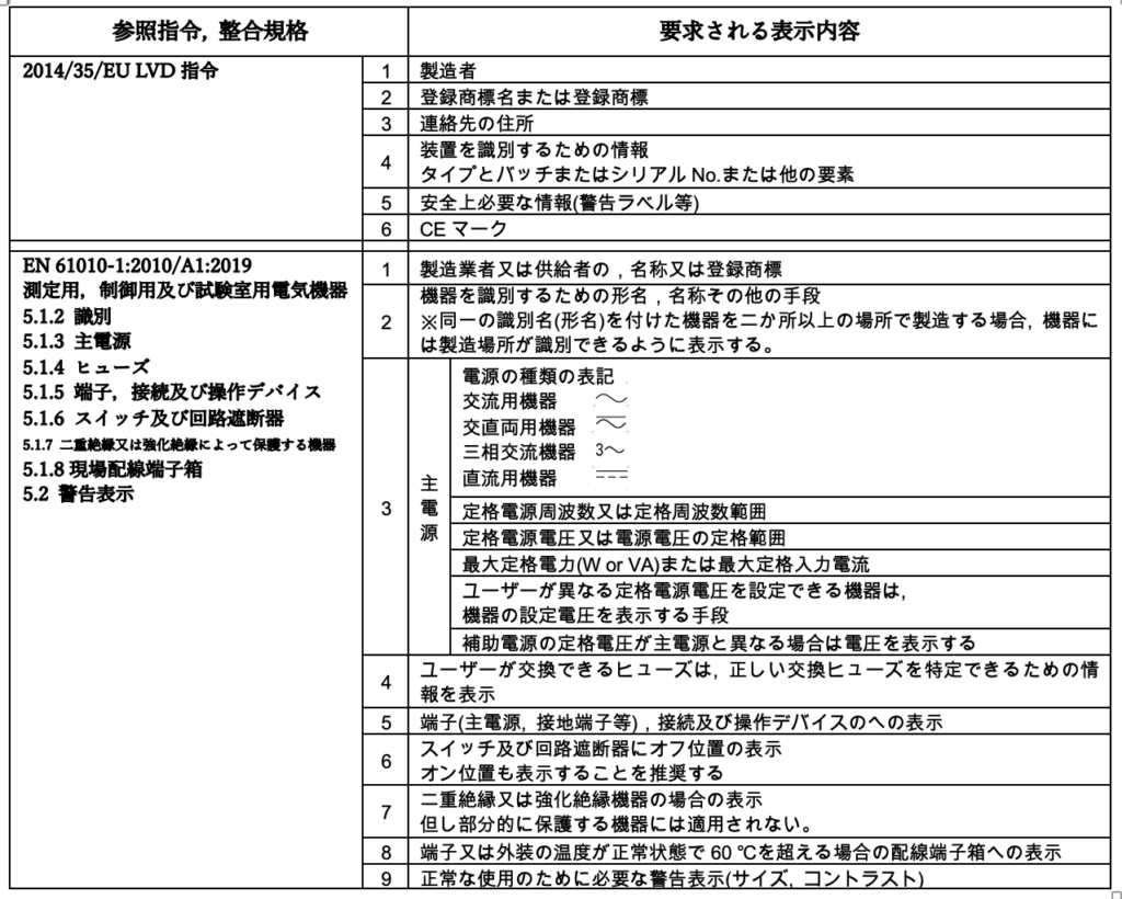
電気機器への表示記載事項まとめ
以下記載が必要な表示のまとめになります。
その他
LVD指令へは下記HPのリンクから参照できます。
https://emcengineer.net/189/
LVD指令のガイドライン
https://ec.europa.eu/docsroom/documents/31221
ヒューズの特性表記の例 参考
https://www.swe-check.com.au/pages/learn_fuse_markings.php


コメント